Brendan Barrett
Structural Option
Building Name: Brendan Iribe Center for Computer Science and Innovation
Location: College Park, MD
Building Occupant Name: University of Maryland
Building function: University Academic Building
Size: 215,600 square feet
Number of stories: 7 floors + basement
Expected Opening: 2018
Cost Information: Cost is being withheld at owner’s request
Project Delivery Method: Design-Bid-Build
General Building Data
Project Team
Owner: University of Maryland
Architect: HDR Architecture, Inc.
General Contractor: Whiting-Turner
Civil Engineer: A Morton Thomas and Associates
Structural Engineer: Hope Furrer Associates
MEP Engineer: Setty Associates
Lighting Consultant: MCLA
Audiovisual Consultant: The Sextant Group
Landscape Architect: Mahan Rykiel
Fire Protection: GHD
Interior Design: DP+ Partners


Architecture
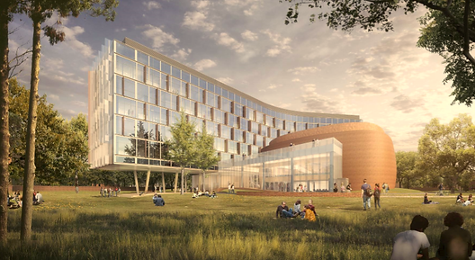
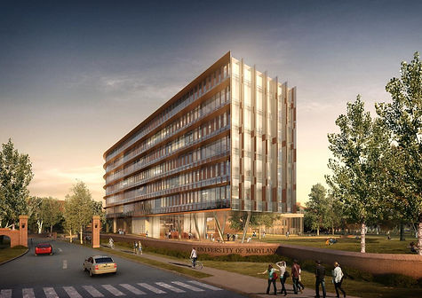
The Brendan Iribe Center for Computer Science and Innovation will be a new computer science building located on campus at the University of Maryland. The University of Maryland is consistently ranked as one of the 15 best computer science universities in the world, and this building will be instrumental in establishing the University of Maryland as the leader in the field of virtual reality and computer science research. A seven story main tower and an auditorium connected via a lobby comprise this building. The main tower will include research labs, classrooms, offices, conference rooms, and a café, while the 300 seat auditorium will provide the university a venue to showcase the latest advancements in virtual reality.
Codes and Zoning
The major national model codes for this project include: 2015 International Building Code, ASCE 7-10, ACI 318-14, and 2012 National Fire Protection Association. This project follows Prince George’s County zoning laws.
Historical Requirements
Historical requirements are not applicable for this project.
Building Enclosure
Facade:
South Façade Floors 2-6: A unitized curtain wall system with four point structural glazed installation at each floor level. At each floor level an insulated shadow-box enclosure will connect each window wall. A continuous metal sun shade will then extend beyond the glass face. Glazing will have custom ceramic frit pattern integrated in the insulated units.
Ground Floor façade at main building tower and lobby connector: Structural glass curtain wall system spanning from floor to floor
East and West Façade Floors 2-6: Similar to the south façade with a glazed unitized curtain wall system with glass fins with frit pattern mounted vertically. Glazing will be installed with four point structural glazed installation.
North Façade Floors 2-6: Similar to the south façade where extended façade elements will have periotic glass vertical fins enclosures integrated within the aluminum curtain wall system.
East Soffit: Polished stainless steel panels on a hidden clip system
Auditorium: Brick masonry veneer on cold form metal framed wall system. Exterior sheathing within cavity wall will be developed and constructed to the curved shape of the building to ensure proper placement of masonry veneer.

Roof:
Main roof above office area and mechanical wing will be a low impact "green roof" with planted seedum in minimum 6 inches of soil. Green roof first floor connector to be an "Intensive Roofing" system will be poured membrane roof system. Roof drainage system will be designed to mitigate storm water drainage. Roof drainage will be combination of main roof leader drains with secondary emergency drain leaders for each drainage area.
Sustainability
Several sustainable design goals include:
-
-Restoring 25 % or more of the non-building footprint building site area with native or adaptive vegetation
-
-50% of site hardscape shall have 0.3 solar reflectance, shaded structures, tree shading or previous pavement
-
-Soils disturbed during construction shall meet organic matter, compaction and other soil restoration criteria
-
-70% of the total building materials used in the project shall contain recycled content, recyclable building materials, biobased building materials or indigenous materials
-
-50 % or more of the newly landscaped area shall be planted with native or climate adaptive species
Primary Engineering Systems
Structural
Gravity System: The Brendan Iribe Center for Computer Science & Innovation utilizes composite steel framing with 3 ¼” lightweight concrete topping on 3” 20 gage galvanized metal deck (6 ¼” total thickness) reinforced with 6x6-W2.0 x 2.0 welded wire reinforcement.Due to the curvilinear nature of the building, structural bays are of varied sizes. Girders running east-west of the building span approximately 30 feet, while infill beams range in size from 20’ – 42’ based on the column layout and location in the building. Typical girders range from W 21x44 to W 27x84 while infill beams range fromW 12x19 to W 24x76. Columns range in size from W 12 x 53 to W 14 x 311, and are spliced every two stories.
Lateral System: The lateral system consists of ordinary moment frames and ordinary braced frames located in the eastern and western wing of the main tower and in the auditorium.Moment frames are either W 24 x 55 or W 24 x 68 and span 8 to 24 feet. There are several different braced frame configurations including diagonal, double diagonal and chevron bracing. The bracing members are typically W 10 x 112, W 12 x 120, or HSS 20 x 12 x ½. Lateral columns range from W 14 x 159 to W 14 x 370.
Foundation: The foundation for this project consists of mat foundations and shallow spread footings. The bottoms of all exterior footings are 4’ below finished grade to reach frost depth. A minimum net allowable bearing capacity of 5000 PSF has been used for design. Due to the partial basement being located within 500 year flood plain, the walls and slab on grade are designed for hydrostatic pressure. As a result, a 48” thick mat slab is located 3’ below the top of the finished basement floor. Continuous wall footings are 3’ wide x 1’-6” deep and reinforced with 3 # 5 bars.
bars.
Mechanical
High pressure steam for the building is generated at UMD College Park’s Central Campus Power/Boiler Plant. There are six air-handling units ranging in size from 18,000-30,000 CFM providing ventilation located in the penthouse. Two 530 ton chillers located in the basement, and two cooling towers located on the roof provide the air conditioning.
Lighting/Electrical
The electrical distribution system includes 480Y/277 volt 4000 A main switchgear located on the first floor. Transformers located on the first floor provide 120/208 V for receptacles. There is also a 480Y/277 volt indoor natural gas generator located on the first floor.
The majority of the artificial ambient lighting is generated by linear TLCP fluorescent lamp or LED sources. The tubular fluorescent lighting is T5 or T5HO lamps, while the LED light sources are used for downlight and accent applications. For exterior lighting, landscape lighting is designed to match the function of landscape zones. The outdoor lighting is controlled via central photocell to turn the lights on, and a 7 day/24 hour time clock to turn the lights off.
Construction Considerations
Construction will start in 2016 and conclude in 2018 and utilize tower cranes. Currently the site consists of a parking lot and green space, and the parking lot will be demolished and the flood plain will be restored to a more natural condition. The total cost of the project is being withheld at the owner’s request.
Additional Engineering Systems
Fire Protection
The entire building is fully sprinkled with a hydraulically designed automatic wet pipe sprinkler system in each stairwell. This system encompasses all occupied spaces of the building, including elevator machine rooms, mechanical equipment rooms, and electrical equipment rooms. This sprinkler system is zoned by floors, which are supplied from standpipes located within each stairwell.
Transportation
The elevator core is located at the center of the main tower of the building along the main corridor. This elevator core provides transportation from the ground floor to the 5th floor. There is also a stair case that surrounds the elevator core, as well as a stairwell located at the east and west end of the tower.
Telecommunications
Telecommunications infrastructure for this project include pathways and spaces, telecommunication rooms, and structured cabling throughout the building. Information technologies require dedicated rooms on each floor to house equipment racks, network switches, optical fiber terminations and copper cabling path panels. These spaces, known as Equipment Rooms and Telecommunications Rooms provide for the organized and logical distribution of low voltage communications signals within the building and are designed to be flexible and scalable. The structured cabling consists of a wired building network that uses a common cable that support all communications needs for various equipment such as computer networks, voice systems, surveillance video, and building automation system.